Gooseneck punches — commonly referred to as “gooseneck tools” — are used when bending narrow C- and U-shaped profiles. In this article, we take a closer look at this type of tooling and explain in which situations it becomes essential.
What Characterizes a Gooseneck Punch?
Gooseneck punches feature a cutout (relief space) in their working zone. This modified geometry allows the operator to form more complex part shapes.
Compared to standard straight punches, gooseneck punches are typically larger and heavier. One practical consequence of their design is a lower allowable load per meter, meaning they withstand less tonnage than their straight counterparts.

Example of a Gooseneck Punch
Channels, Profiles, U-Shapes — Applications for Gooseneck Punches
To achieve a narrow U or C profile, a standard straight punch usually cannot be used.
The reason is simple: during bending, the already-formed flange would collide with the front face of the punch.
Gooseneck punches solve this problem because their internal relief avoids contact with the bent section of the workpiece, allowing the bend to be completed without interference.
Without this type of punch in your tooling selection, producing such closed or narrow geometries from a single piece of material would be impossible.

Convenience and Expanded Bending Capabilities
Gooseneck punches significantly broaden the range of geometries that can be formed on a press brake. As a result, the shop becomes more versatile and competitive.
When a gooseneck punch is used together with an inverted clamp, operators can optimize the bending of C-profiles. This setup allows the operator to directly control both outer dimensions of the part, while only the center dimension becomes a “resulting value.”
This provides:
-
quicker dimensional corrections,
-
higher accuracy,
-
and consistent results even if bending angles vary slightly.

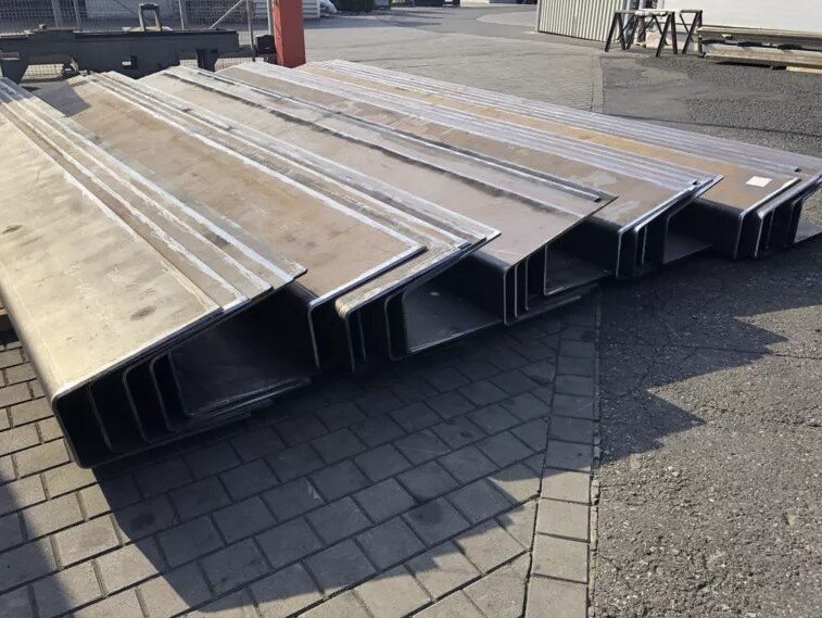
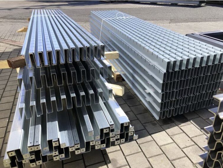
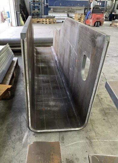
Gooseneck Punches — Practical Applications
The images below show several situations where gooseneck punches are used in real production environments. (Source: USM Czernikowo)